We have come a long way since ECDIS was brought into our lives.
In the initial days we were just struggling to keep the ENCs updated on ECDIS.
But that is the thing of the past. Most of us know this drill at the back of hands now.
And I have covered quite a few of articles on updating and keeping the ENCs up to date.
Even during the third party inspections, the inspectors are now focussing on the ECDIS in detail.
As even they consider that the period for amateur questions on the ECDIS is over.
One of the area that now require detailing is the passage planning on ECDIS.
Well, actually there is nothing different in the passage planning on ECDIS.
More or less it is same as what we used to do on paper charts. But still it is so much different.
In this blog we will discuss the 7 elements which once plotted would make the passage plan on ECDIS stand out.
Let us start.
1. Route
The first element that you all may have guessed is the route.
And when it comes to choosing the route, there is nothing different from what we do even when were using paper charts.
We need to find the information from all the publications available.
Here is an article that I had written sometime back on using the publications to find the best route to follow.
And once we have all the information, we need to use that to decide the route.
The route that we decide must follow all the company requirements and must be in accordance with the industry guidelines.
Let us see how to go about creating the route on ECDIS (JRC ECDIS).
On the top menu, go to Route -> Route Planning -> Graphical editor.
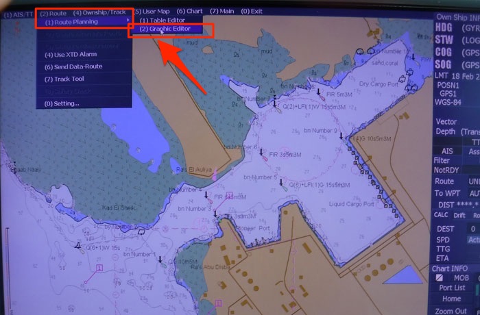
Then it is just like drawing a route on the paper chart. Just take the cursor on the starting point and keep on clicking wherever you wish to create a waypoint.
![]()
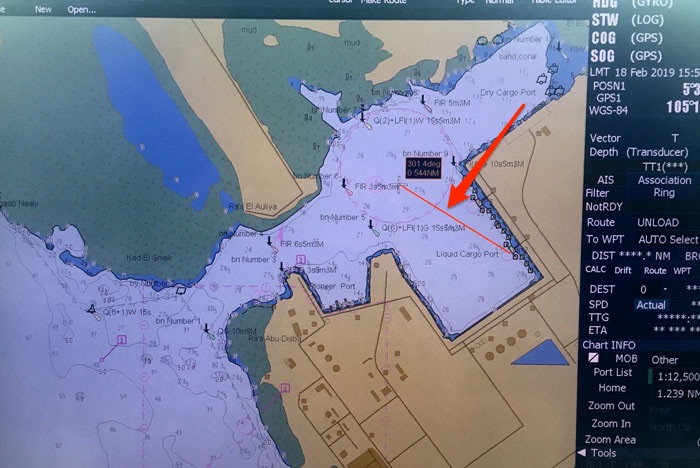
When doing that, it would be easier to zoom out and choose a little smaller scale to get the idea of where we need to head to.
And then you can keep on zooming in and out as and when required while creating the route![]()
Once you have created the complete route, you can save the route.
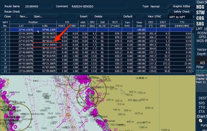
The waypoints created by the graphical editor would most likely be upto 3 decimal places. For ease of reference, you may want to change these waypoints to upto one decimal place.
For that you can go to Route -> Route planning – > table editor and open the recently saved route.
From the table, you can fine-tune the waypoints. For example, you can change the longitude 38 Deg 57.999′ to 39 Degrees.
![]()
2. Route check.
We now need to make sure that the route that we have drawn is not passing through any dangers.
But before we do that, we need to set the safety settings on ECDIS according to our draft for the next voyage.
I have written a blog on ECDIS safety settings in detail and check that out about more information on ECDIS safety settings.
Now to check the route, each ECDIS has a function called “Route check” or “Safety Check”.
Go to the Route -> Route Planning -> Table editor and open the route that you have created for the present voyage.
In the editor, enter the value of the cross track error that you wish to have or that your company or master allows.
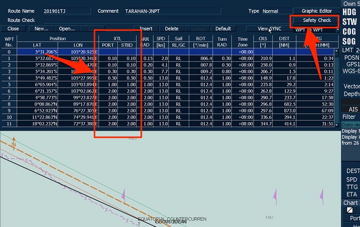
The route check function will check if the route (along with the cross track distance) is not passing through any dangers to navigation.
![]()
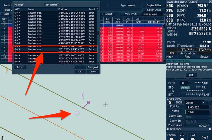
When we have entered the cross track distances for each leg, click on the “Safety Check”.
The ECDIS will check the route and display all the errors that user need to check physically for.
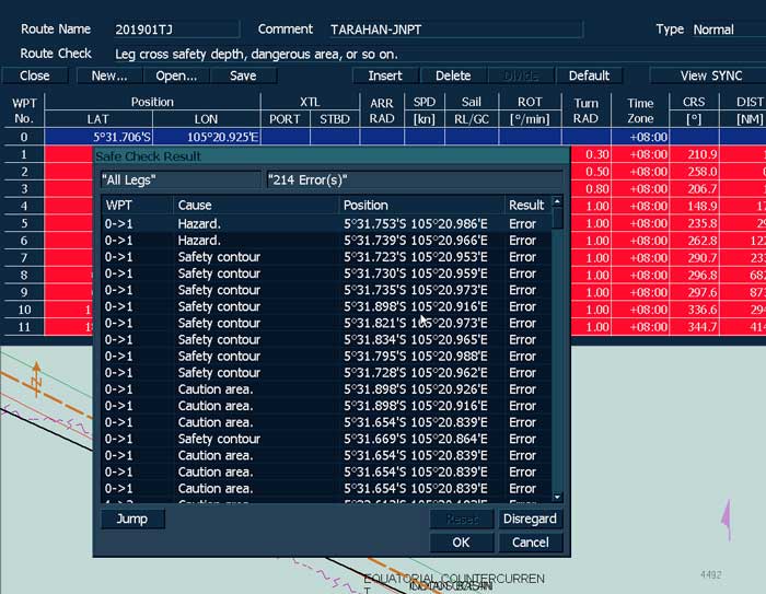
We need to check these error by going to that area of the passage plan on ECDIS.
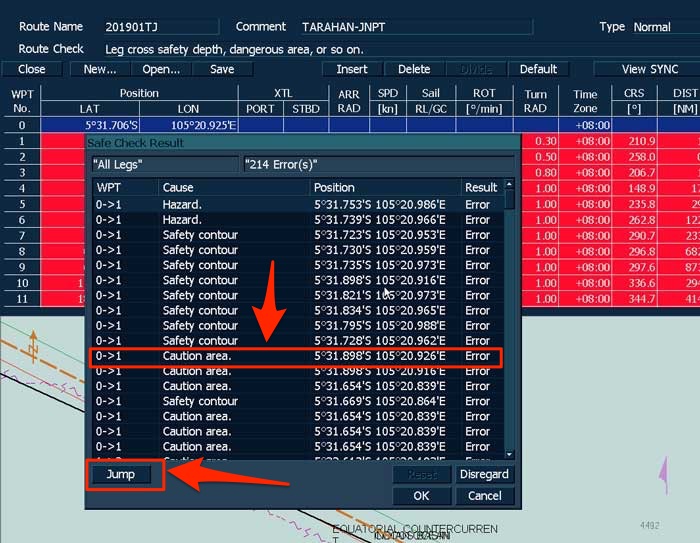
To do that just select the error and click on Jump.
![]()
This will take the ECDIS to the area of the passage plan where this error is detected.
![]()
For example, if the error is about a caution area, check the detail of the caution area.
This can be done by right-clicking on the ENC and choosing “S-57/C-Map/ARCS Information” and then clicking on the “caution area” symbol.
After assessing the information, Modify the route if required. Otherwise, check the next error.
After checking each error, click on that error and click “disregard”.
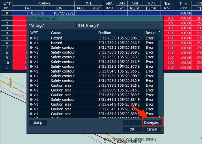
After you have checked all errors, click on “Ok” and save the route.
You have now completed the route check.
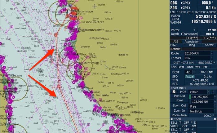
3. Parallel Indexing
Parallel index distances must be marked from the fixed objects on the route.
In the open sea, it is wise to choose any fixed object up to a range of 24 miles or less for marking the parallel index lines.
As your radar will be in the range of less than 12 miles in coastal waters, you can choose to mark parallel index lines from any fixed objects in that range.
And as we all know, the parallel indexing must not be done with floating objects like buoys.
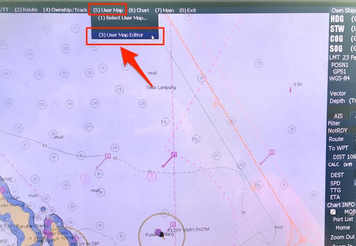
To mark the parallel index lines we use “user map” feature of the ECDIS.
Go to User map -> User map editor.
![]()
Click on New -> Simple Line and then take the cursor to the point (landmark) from where you want to draw the Parallel index line.
Draw the first line parallel to the course line and then 90 degrees to that to join it to the course line.
![]()
You can then click on the “property” on the right corner and change the line color and thickness etc.
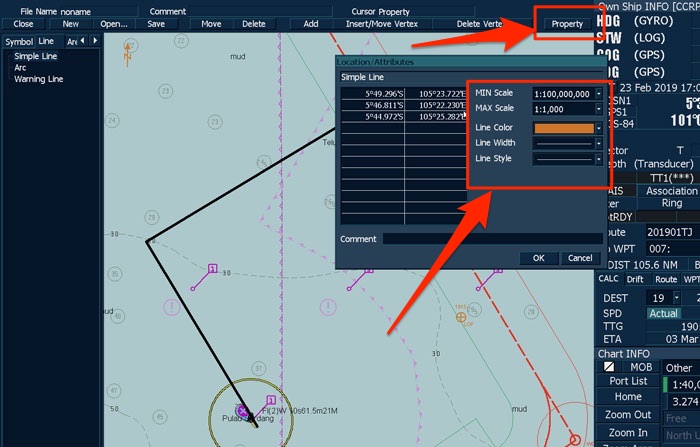
It is better to have the color of the PI-line something other than the course line so that course line can easily be recognized during the voyage by the navigators.
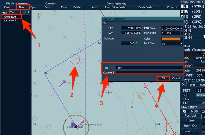
Now we need to write the Parallel Index distance for the PI that we have drawn just now.
Click on New -> Small text. Click at the location near to the PI line where you want the text to appear and then write the text such as “P.I. 3.2 NM.
![]()
Of course, we need to measure this distance first and write an accurate distance.
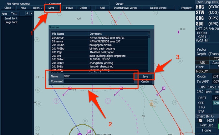
You can then click on “OK” and then “Save” on the top menu.
Just enter the name that you want to give to this user map (may be the voyage number) and then click on “Save” to save the user map.
This same user map will be edited for all other markings that you need to plot on the ENCs.
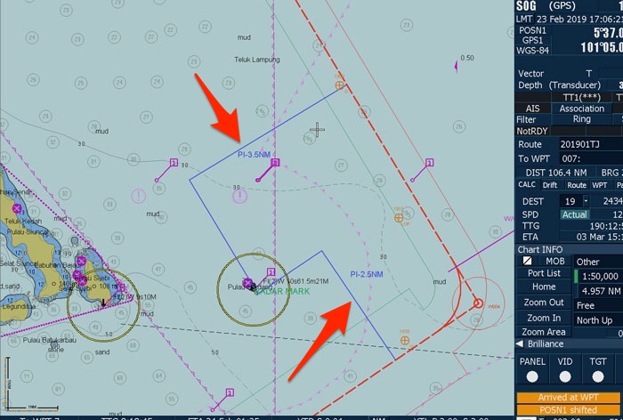
Now finish plotting all the parallel indexing lines and distances from all the radar conspicuous fixed objects on the voyage.
![]()
4. NO GO Areas
We are required to mark the no-go areas along our route.
These are the areas that are the danger to navigation and we must not navigate into.
But let us say there is a wreck (or shallow waters) about 50NM from our planned route. Do we need to mark this as “No-Go area”?
On a paper chart, the answer to this question was simple.
And the answer was, Yes, we do need to mark it as no go area if it is on voyage chart.
But the ENCs on ECDIS are seamless and the same logic does not apply on ECDIS.
So what is the maximum distance that we need to mark the no-go area upto?
Well, ideally this distance should be provided in the company’s navigation manual.
Alas, most certainly you will not find it there.
So, in the case, a distance can be decided by the master and the same communicated to the navigating officers.
If we have decided the distance of 50NM, we need to mark the No-Go areas in the range of 50NM from our route.
The no go areas must not be marked excessively.
What I commonly see that we sometimes mark the entire shallow water contour as the no go area.
This is wrong because
- It is not that we cannot cross the shallow contour. We can. The only thing we cannot do is run over the safety depth. And thus the shallow contour is not a no go area.
- Even if we consider this as a no go area, the distinction of this area is already visible with a different color. Why clutter the ENC further?
The marking for no go area needs to be done for something that the navigator could miss.
Something like an isolated danger, wreck, depth area or an area like with oil rigs that vessel needs to avoid.
We need to identify all such areas and mark these as “No-Go Areas”.
To mark the no-go area, go to User Map -> User map editor and open the user map that you have created for the present voyage.
By now, you should be able to create lines, shapes and add text in the user map.
To mark the user map you need to use these lines and shapes to mark the area as a No-Go area.
Use your artistic skills to decide which shape or line you need to use for marking of No-Go area.
Once marked, go to the property and change the line color, thickness etc.
![]()
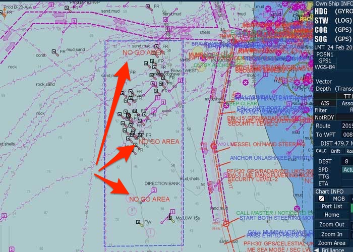
Again use the color as something other than the course line color and thickness slightly lesser than the course line.
Finally, write the text as a No-Go area around the marked area.
![]()
5. Wheel over position
Whenever there is a large alteration of the course, we need to mark a wheel over position.
This is the position on our initial course at which we need to start altering the course at a pre-planned rate of turn to arrive at the next desired course without running into the danger.
![]()
Marking of wheel over position is part of the passage planning.
But how to mark this on ECDIS?
The wheel over position depends upon the speed of the vessel and rate of turn during alteration of course.
As the turning of the ship is in form of an arc of a circle, there is another element that is involved: Radius of turn.
There is a relation between these three terms.
ROT = Speed of the ship/Radius of turn
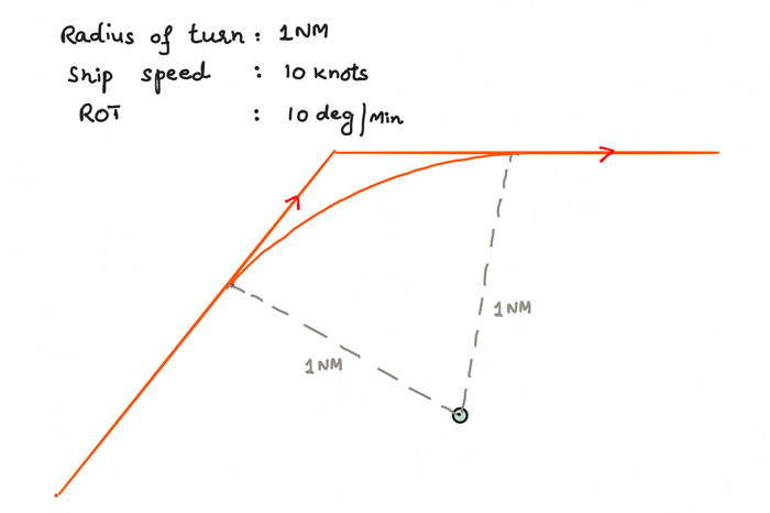
But what the officer on watch need to know when altering the course?
They need to know at what position he should start altering the course and with what rate of turn should they alter the course.
We must keep in mind that this arc is a kind of our course during the course alteration process.
The arc would remain the same if the radius of turn would remain the same and we do not change that.
For this reason, we need to define the value for the radius of turn and keep this same once planned.
Usually, we keep the radius of turn of 1NM as constant.
Now with this, ROT becomes equal to the ship speed.
![]()
While passage planning on ECDIS, we need to define the value of the radius of turn and ship’s speed at each leg.
To do that, go to the route – > Route planning -> table editor and open the route you created for the voyage.
Under each waypoint, enter the value of “Turn Rad” and “speed”.
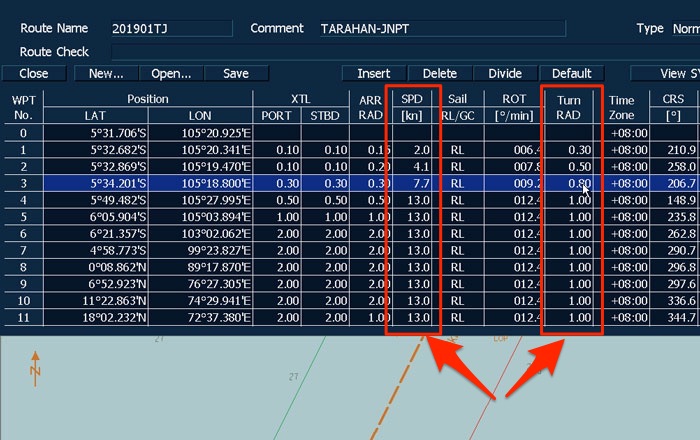
![]()
This would create the arc for the alteration of course for each leg in the route.
But that is not enough. There is another element that we need to address.
Once we put the rudder on one side to turn the vessel, the vessel will take some time to start turning. We need to allow this while marking of the wheel over position.
This information is provided in the maneuvering booklet and is given in terms of “distance moved as the length of the ship before vessel start turning”.
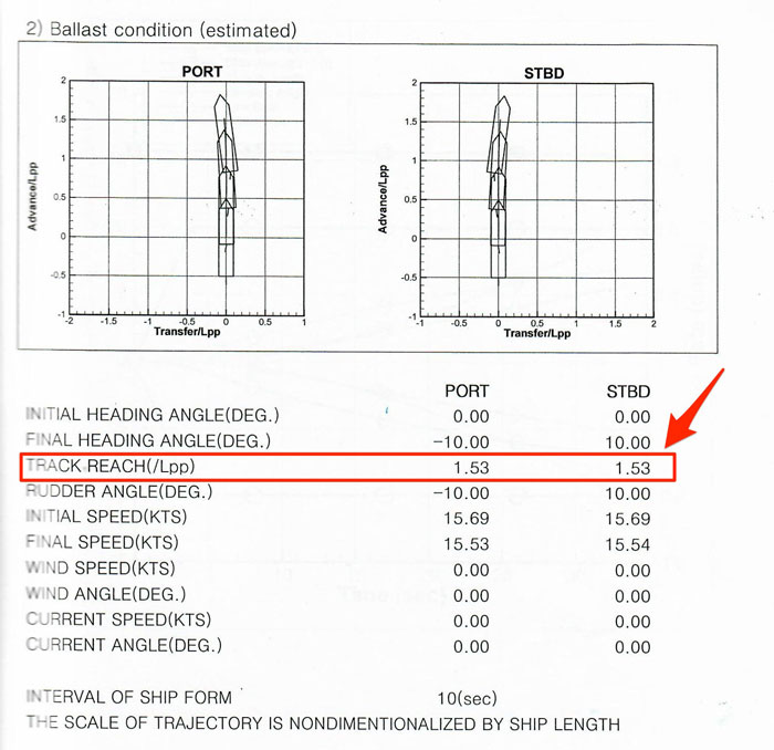
It is generally between one to two lengths of the ship.
![]()
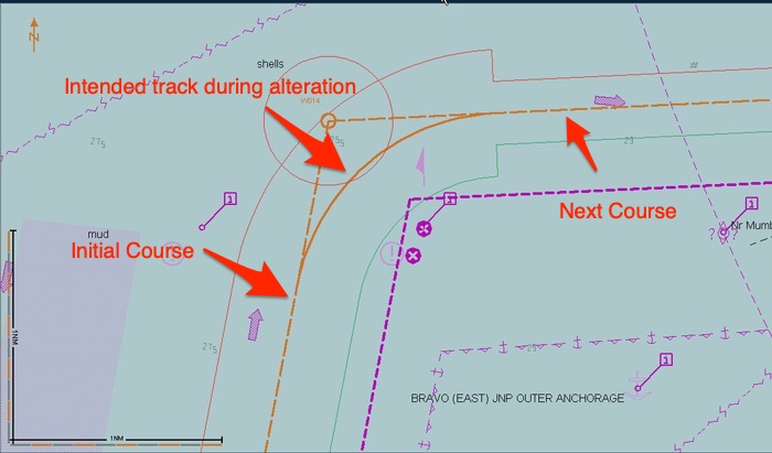
The wheel over position needs to be marked at a distance by that much from the start of the course alteration arc.
It may not be possible to measure that small distance but just make sure it is justifiable.
And to mark that we need to edit the same user chart that we have created for the voyage. We have already discussed about editing the user chart.
Here is how marking of the wheel over line would look like.
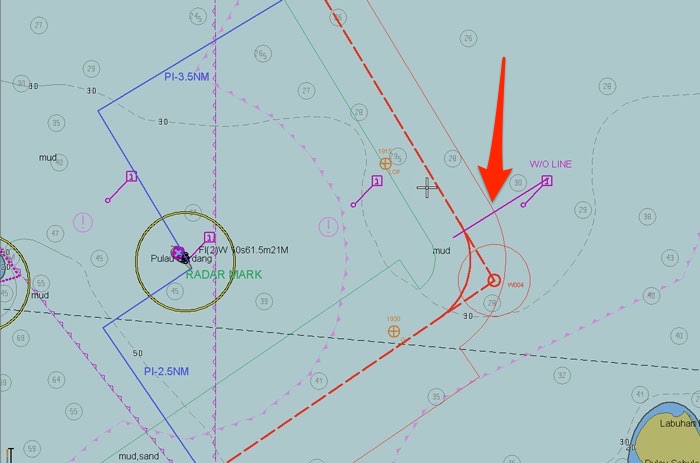
![]()
Wheel over range and bearing
If there is a fixed object near the wheel over position from which radar bearing/range or visual bearing can be taken, we need to define the wheel over position with respect to bearing/range from this object.
Again, the marking of this line will be by editing the same user chart.
Then we need to draw a line from the fixed object to the wheel over position and measure the bearing and distance from wheel over position to this fixed object.
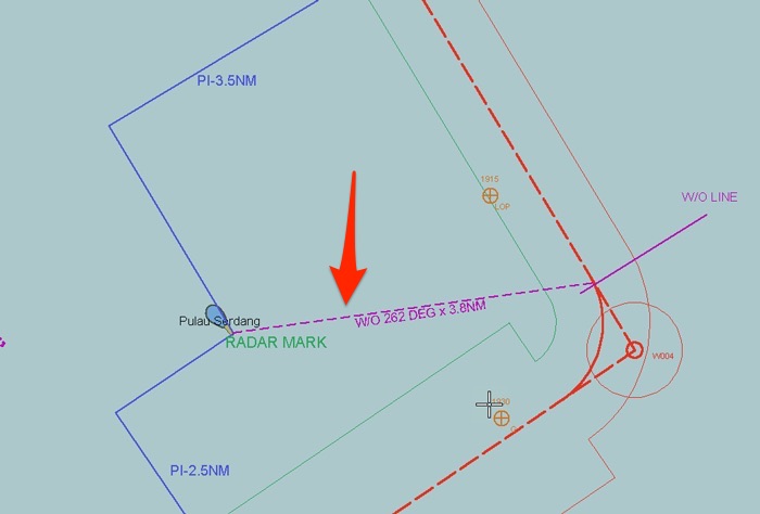
We can then edit the user chart further to write the text with information about bearing and distance.
![]()
6. Abort point and point of no return
I have written in length about “abort point and point of no return” in a different blog.
Read this blog if you wish to understand about the marking of abort point and point of no return.
Marking of abort point on ECDIS is not different than marking on paper chart except here again we will use the user chart option for marking instead of pencil.
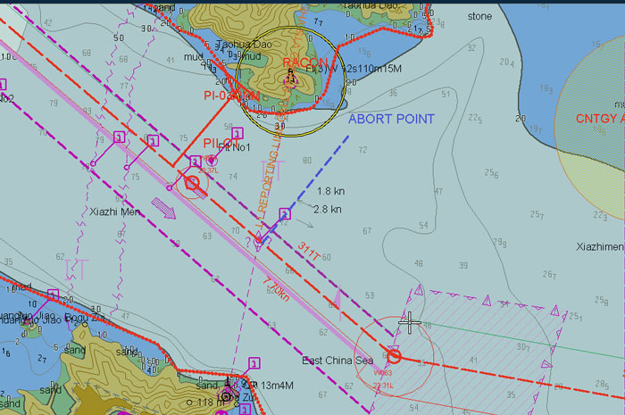
![]()
7. Position plotting interval
I have in written in length about “position fixing and position plotting interval” too.
Here is the link to that blog.
“Position fixing interval” is the maximum interval between two position fixes. So if in a particular section of the passage, we have agreed to the PFI of 01 hours, we must plot the ship’s position at least every hour.
During the passage planning, we need to decide the position plotting interval and methods.
This information needs to be provided at each leg of the route.
On ECDIS we just need to edit the same user chart to include the text about position plotting interval and methods at each leg.
8. Other information
Then there is other information that we need to write on the ECDIS. These include
- Watch levels
- Contingency anchorages
- Security levels and hardening measures
- Reporting requirements
- Calling the master
- The point at which notice to be given to Engine room
![]()
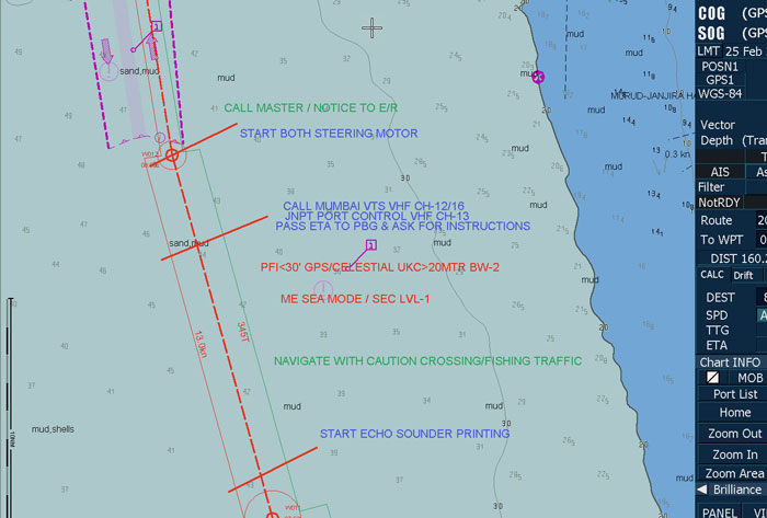
Even though all this information are to be in text form but I will expand on these points in future blogs.
Conclusion
We have mastered the art of Passage planning on paper charts.
After all we had been doing this for decades.
However passage planning on ECDIS is comparatively a new thing and is evolving.
Conceptually this is no different from the passage planning on paper chart but we must understand the ECDIS specific elements to plan the passage on ECDIS.
Share this:

About Capt Rajeev Jassal
Capt. Rajeev Jassal has sailed for over 28 years mainly on crude oil, product and chemical tankers. He holds MBA in shipping & Logistics degree from London. He has done extensive research on quantitatively measuring Safety culture onboard and safety climate ashore which he believes is the most important element for safer shipping.
Search Blog
42 Comments


Great article sir! Nicely explained. One question sir, for position fixing is there a criteria for position fixing with regards to the distance of fixed objects observed visually or by radar? Or what is the maximum allowable distance for fixing position?

For Visual, as far as eyes can clearly see and take bearing. As Radars are used effectively at 12NM range, the PI can be drawn from objects about 18NM (Considering Radar off center).
Very much appreciated your blogs sir. I hope many experienced seafarers will also impart their vast knowledge as these are very helpful to us, new seafarers! Two thumbs up!
Thanks Earl...
Thank you so much for your great article. Also tell me wt is to be done when ecdis shows No overlay AIO for some area.
AIO is basically the computerized version of T&P notices and other navigational warnings, this is where the OOWs diligence in checking received EGC and navtex messages come in. When no AIO overlay is available, be sure to check all sources available for possible warnings and notices in the area, plot them accordingly, file and affix signature. It is the officer's responsibility to exhaust all approved references in keeping ENCs up to date.
Nice article. Regarding the PI topic: what you have plotted on ECDIS is not a PI; it is a kind of user symbol. A PI "travels" together with the vessel. There is the info necessary to set up the Radar display for the respective PI. About the No Go Area topic, the ENC provides sufficient info to inform the user (OOW) that there is an area you must avoid. We may observe the perimeter on chart. There is no need to additionally write "No go". We just need to "interogate" the chart; of course I agree we must write "no go" where the chart doesn't say that and we cannot go into that; for instance a draft restriction ( VLCC case). Very nice and useful article.
well said

Dear Captain, excellent article!! Many thanks.
YOU ARE SO STUPIED.IF YOU STEALING THE ARTICLE AND SEND IT TO YOUR FLEET,MENTION THE ORIGINAL AUTHOR AT LEAST.AND DO NOT SIGN AFTER LIKE YOU WROTE IT BY YOUSELF.CAPT Rajeev Jassal THIS GUY STOLE YOUR ARTICLES WITHOUT MENTION YOUR NAME.
Thx for the great topic! Only few things I would like to clarify: 1. On ECDIS JRC - Wheel Over Line it’s plotted automatically along the route, I mean, we can set turn 1 NM and it will draw. 2. Is it necessary to write to many “no go area “ ? Let’s say for safety contour, ECDIS gives OOW clear info the safe and unsafe water. Yes there are a lot of cases when we have to cross safety contour because of ENC producer/hydrographic office and yes we have to draw warning lines/area to mark our real safety contour which is usually our safety depth and when look ahead will “touch” it
More bullshit you make, more paper work u do, you are more safer in case of vetting... based on 16 yrs of experience
Sir , Your blogs are very useful onboard and ashore (exams) alike. Waiting for your new blogs as usual. Thanks a lot.
Excellent blog sir... This contract i was new to jrc ecdis... I have one query regarding PI on jrc ecdis... How can we monitor PI during our voyage on jrc ecdis... Since in model 901 B Jrc i couldnt find the PI lines available... But on on furuno we had option for that.. . So after drawing PI on usermap how can we monitor effectively when passing close to that object on jrc ecdis...
You do not use PI to monitor Position on an ECDIS. Just like paper charts, PI distances are marked on ECDIS as information to be used for position monitoring by Radar/ARPA.
I share the same view as Mr. Kumar but don't know whether our understanding is correct. Can Mr. Rajeev Jassal or any other gentleman confirm to us or leave your comments? The object used as the reference for PI will deviate from the index line on Radar whenever the ship deviates from her course lie. Will the same thing happen also on ENC? If the answer is 'yes' plotting PI on ECDIS makes some sense; otherwise, giving more meaningless workload to OOW only, I guess. You gentlemen's comments are welcome. Thanks a lot.
Great article sir
Great article sir Could you show us also passage plan on Ecdis furuno fmd 3200?
hi sir , i do normally get 100s of errors on route check how to tackle the same.
Dear Capt Rajeev Jassal, First of all I appreciate with you kind consideration regarding this education articles. I have started to read all of them one by one with caution. Regarding this article as a Second officer who learnt navigation on ECDIS , I want to mention that we need to call 'Position Verification" rather than calling position intervals or fixing anymore. Due to real time navigation option of ECDIS we dont need to think or verify the current ship position continuously. Checking HDOP of GPS every 15 min while doing coastal navigation which can be supported by Radar fixes and PI's will be more than enough to clarify ships position.

Dear Sir , good question.
Dear Sir, thanks for the nice article in this wonderful website. One small thing I would like to mention though. Those sharing options (Fb, tweeter etc.) are overlapping the article and obstructing the view. Would you kindly relocate them?
Very insightful description. However, are the ECDIS units required t be independent of each other? If, so then position fixing and other changes have to be carried out on both separately which takes time and focus away from watchkeeping. If not, then tendency is, not to verify that the other unit is updated accordingly...Pls clarify......
we could cross safety contours provided we follow methods 1 or 2. it is the safety depth that we need to be wary of.
Dear sir Good day This blog is very help full for us thank-you so much sir . Kindly any one may send this blog in PDF on my email ID singh.Akhil627@gmail.com
Good article sir. Wheel over and turn radius should be taken more into consideration. People forget that they are not escorted by tugboats from port to port and sometimes create passage plans with ROT 40° by not editing turn radius or speed
why it is showing all the time Warning (UNACK:1) Cause: STW and the othere warning is Cause: Position(GPS1) not Differential
(1) Can anyone explain me step by step how to do the monthly back up of ecdis? (2) How to send the test message in SATCOM and also "RCC drill" format . Because when i am sending the test message in the ship email id it showing the status "Delivered" , but really i am not receiving any test message. say how i can solve this issue? please help
Thank you sir. Your blog is very informative and well delivered, also we share same type of ECDIS so it's been a great help. :D
I would like to ask if in the ECDIS can we calculate the great circle route ?
Dear sir i have some queries 1. What is arrival radius in Ecdis and how much we should keep? 2. Shall we keep XTL limits more or less...like for open sea We can keep 1 mile or 0.50 miles also, how to decide what we should keep?? 3. In ECDIS in rta format WOL is already marked but in route with file rtn, arrival radius is given ...so first explain which format we should use and why? And if we use rtn format where arrival radius is given so in that case we nees to mark WOL by user map???
Shanghai Gebo Packing Machinery Co., Limited is a professional and leading Bag Inserter and Sealing Machine Supplier in China
good day sir! thanks to you better world has made on maritime! it is out of topic! but im so curious about the amended passage planing procedure. all passage plans are have been made berth to berth. what if modifications are made during the voyage? do i have to create all waypoints that already passed before? i think amended passage plan should be made from clsoest waypoint to berth. i cant find any instruction about this on B.P.G, B.T.M. etc... can you tell me where can i find details among the international rules or guidance
Nice article , thank you sir
Sir, i would like to ask, now i experience that on ecdis the vessel is on course line, but below it indicates that XTD is 1.0nm off Stbd? What do i need to check?
Hi sir...hope u remeber me...hope u have forgotten me as it has been a very long time...anyways sir...in ECDIS do we still need to plot NLT and NMT...
At point 4. NO GO Areas - correct Shallow Water Contour / Shallow Contour and write Safety Contour to avoid confusions. If you cross Shallow Contour, you are aground. You can cross Safety Contour if you are aware of the Safety Depth.
Dear sir good day, can you please write an article regarding Mandatory and voluntary ships reporting system.
Thanks for sharing sir g! Even though it just basic article also fruitful for new beginner
Leave Comment
More things to do on myseatime
MySeaTime Blogs
Learn the difficult concepts of sailing described in a easy and story-telling way. These detailed and well researched articles provides value reading for all ranks.

Seafarers Question Answers
Ask or answer a question on this forum. Knowledge dies if it remains in our head. Share your knowledge by writing answers to the question

MySeaTime Podcast
This podcast on the maritime matters will provide value to the listeners. Short, crisp and full of value. Stay tuned for this section.
Sir,GPS positions are plotted for every minute on ecdis hence plotting intervals are normally not marked these days. In case you are referring to radar/visual fixes it needs to be highlighted.
Plotting interval is not only about plotting of ship's position on ECDIS, it is also about OOW checking if the ship is proceeding as planned. So even if the GPS position is being plotted automatically, PPI need to be mentioned.
Rajeev, that is just a bureaucracy for insurance houses... indeed... so OOW does not have other jobs other to plot the position? OOW is continuosly monitoring the vessel movement through water, this is just additional distract to reduce attention