Radars on board are probably the most used equipment during navigation. It is a good tool for the look out. We are so much dependent on the Radar that sometimes we use it more than we use our eyes for look out. But what if I say that radar is also most under utilized equipment on board. Don’t believe me, then try answering this questions in yes or no.
Most of the times I do not use any controls other than gain, sea and rain.
Did you say Yes or No ?
Whatever your answer, but most of the people use only these three controls for setting up a radar. And that is undeniable fact. This is even when Radars have so much more than these three controls. And when we do not use all the controls to set the picture, the picture might look cluttered.
Through this post, I want to discuss how best we can have radars paint a perfect picture of all the targets.
Basic operation of Radar
Before we start into the controls of the radar, it is important that we know how marine radars operate and some of the terms associated with the operation of radar.
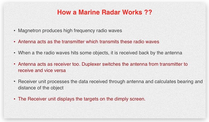
A radio wave is transmitted and received back by the scanner. The time is calculated between transmission and receiving back this wave. The speed of the radio wave is known and thus the receiver unit calculates the distance of the target. After processing, it displays this information on the display screen. The rotating scanner also calculates the bearing of the target and displays on the radar screen.
There are couple of terms related to radar that we need to cover before we proceed further. These are radar resolution and radar sensitivity.
1) Radar Resolution
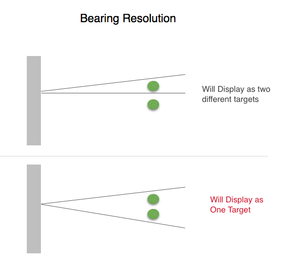
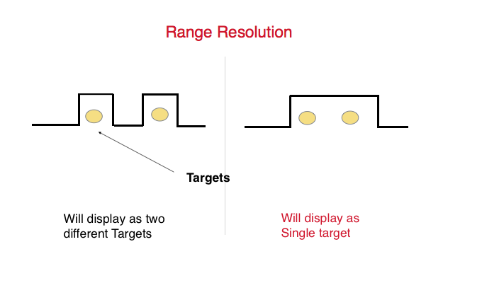
Radar resolution is the ability of the radar to show two targets which are close to each other as separate targets on radar. There are two types of radar resolution. Range resolution and bearing resolution
As the name suggests, better bearing resolution means radar can paint two near targets on same bearing as separate ones.
Bearing resolution depends upon Horizontal beam width of the radio wave.
Same way, better range resolution means radar can paint two close targets (on different bearing) as separate ones. Range resolution depends upon pulse length.
2) Sensitivity
In simple words, Sensitivity of radar is how thick a radar plots the targets. A better sensitivity means a radar can paint even a fishing boat as slightly bigger target. Less sensitivity means there are chances of a fishing boat missing on the radar screen.
Now that we know these terms, lets see how best we can set a radar to display the targets perfectly.
1) Gain, Sea and Rain
This is the easiest one I guess. Easiest because we use it lot of times. And I do not need to elaborate much on these controls. But still for the benefit of few, lets say few word about these controls.
Gain is used to increase the receiving sensitivity of the radar. It need to be adjusted to a level where targets are visible but there is no other interference on the screen.
We use Sea control to reduce the clutter echo caused due to surface of the sea
And we use Rain control to reduce the clutter echo caused by rain.
Let me ask a question. To what level we need to keep these three controls ? For example, Will the Full “Gain” and half “Sea” control levels paint targets with same clarity as Half “Gain” and zero “Sea” control level ?
The answer lies below.
We must use Sea control only when we have moderate to rough sea or when we think that interference on the radar is because of sea state.
Otherwise we should not use the sea control. In the calm sea if we see clutters, it is better to reduce the gain than increase the Sea control. Moreover we should not try to remove the interference at long range with Sea control. This is because the interference from the sea will be at close range only.
The correct way to set these control is as follows
1) Increase the gain to the maximum
2) reduce the sea and Rain controls to the minimum
3) Reduce the gain to a level where most of the clutters are just removed and the targets can be distinguished.
4) If required increase the sea control to reduce the sea clutters near to the center of screen.
2) Pulse Length
Pulse length can be set to Short, medium or Long pulse. Most radars automatically adjust the pulse length according to the selected range. But knowledge of pulse length can help in setting the radar in way to show the targets clearly.
now lets see what each pulse length does..
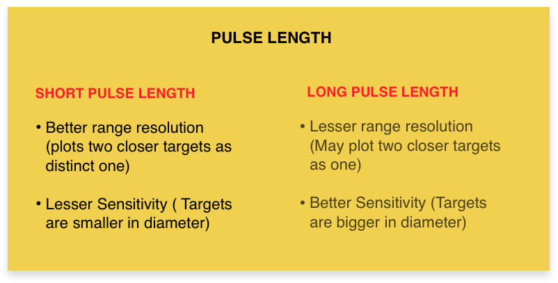
Short pulse: As we saw in range resolution, short pulse offers better range resolution. But as the pulse length is short, sensitivity of the short pulse is lesser compared to long pulse.
Long pulse: Again as we saw in range resolution, long pulse has lesser range resolution but better sensitivity.
Medium pulse off course lies between short pulse and long pulse.
We can conclude that short pulse paints two close targets as separate targets. Also the plotted targets are thinner in diameter.
The long pulse may paint two close targets as a single one. Also the plotted targets are bigger in diameter.
So how we can use this information ?
Ideally short pulse is used in short range (Upto 3NM) and long pulse for long ranges (more than 12NM). But we can use the short pulse in long range and vice-versa.
For example in dense traffic area, if we are using radar on long range, we can use the short pulse so that targets do not overlap.
Same way, in fishing traffic, we can use the long pulse at short range. This will ensure that fishing targets are plotted as more prominently.
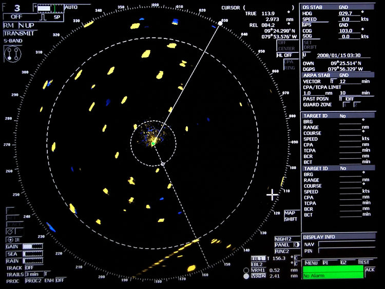
Gain, Sea and rain as well as pulse length is common settings on all the radars. Apart from these there are number of other settings specific to radar make. These setting help to get a perfect picture on radar. Lets see few of these on JRC radar.
Function
We need to set the function level according to the range in use and weather.
Function 1 need to be set on short ranges. Function 2 need to be set on long ranges. And Function 3 need to be set during bad weather.
During bad weather we can use Func 3 along with SEA control. If using both, we need to use the sea control after setting the function level to “Fucn 3”.
To change the Function setting, just click on the Func tab on bottom right corner of the radar.
ENH on/Off
On JRC Radars, this function is called Expand targets. As the name suggests, it expands the size of the targets and targets paints with better echo.
We should only switch off the ENH function when there are too many target in close range to each other. In dense traffic area with ENH on, the targets can overlap and if that is the case, it can be switched off. In open sea ENH should be On.
Again to switch on/off ENH, just click on the ENH on/off tab on left bottom corner of the JRC radar.
PROC setting
On JRC radars we have an option to select processed videos. There are number of option from Proc 1 to proc 3 and then for switching off the Processed video settings.
This function defines the speed of processing and displaying a target on radar screen. When lesser range is set on the radar, the targets moves faster on the screen. So the radar processor has lesser time to process the fast moving targets. This setting adjusts the speed of the processor so that faster moving targets can be painted accurately and promptly.
PROC 1 setting processes the targets faster than PROC 2 and PROC 3 settings.
With PROC 1 setting, the faster moving targets are not missed on the screen.
As the targets moves faster on the radar screen at lower range, PROC 1 is used in range of 1.5 NM or lesser.
Similarly PROC 2 is used for range of 1.5NM and 3NM.
We should use PROC 3 when radar is set on range of 3NM or higher.
To set the processed video level, just click on the PROC tab on left bottom corner of the JRC radar. If set correctly, this can reduce the unwanted clutters from the radar to some extent.
Radar Interference
This control reduces the interference caused because of radar signals itself. This is internal interference of the radar and not because of any external factors. This interference is mainly centered near to the ship location on the radar.
Turning IR control on reduces these internal radar interference.
IR can be turned on/off by clicking on the IR tab on the left bottom corner of the JRC radar.
Tests to perform if radar is not plotting targets the way you want
If even after all these settings, you think that there are some targets you are missing. Or the radar is not able to paint the target with sufficient sensitivity. You can perform some of the tests to check if everything is alright with you radar.
Radar Performance test
We need to perform Radar performance test at least every watch. But most of the times navigators fail to perform this test every watch. Sometimes it is not done for weeks and they make the entry in the log book without doing the test.
Radar Performance test checks the transmission and receiving power of the radar. For example if the transmission power of the radar is not enough, radar may not be able to paint some of the target at all. Or radar may only be able to paint the targets with very less sensitivity (faint echoes).
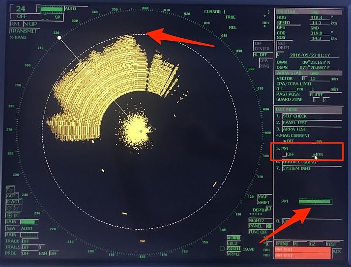
On JRC radar, to perform the performance test, go to Test menu..Choose PM on. This will change the radar range to 24. Increase the gain to full and you can see plume on the radar. Also you can see the bar on the bottom right corner of the radar. Measure the maximum range of the plume on the screen and check the bar length.
On JRC radars, plume range represents the receiving power and bar length represents the transmission power.
These values need to be compared with the actual reference values when the magnetron was new. You can find these values on the sticker usually pasted behind the radar equipment.
But it is possible that you either do not find this sticker or you may find the sticker without any values on it. This is particularly the case when last magnetron was change by ship staff as shore engineer would definately put the values.
If you do not find the initial values, take the maximum values which has the loss of power as zero in the graph.
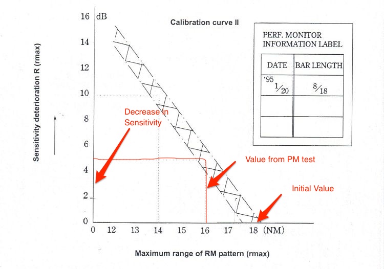
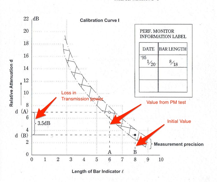
We need to compare these values with the initial one on the graph provided in the manual. These graphs (Called calibration curves) are different for receiver and transmitter power.
By comparing the actual plume length with the initial plume length, we will get the loss in receiver system. This loss is called sensitivity deterioration.
Similarly by comapring the actual bar length with the initial bar length we will get the loss in transmission power. This loss is called relative attenuation of the transmitter system.
If the transmission power is less, the radar may not paint targets at longer range. If receiver sensitivity is less, radar may paint the targets with weak echo on the screen.
In case of less receiver sensitivity, we may use the Long pulse and ENH in all ranges to increase the sensitivity till the time service technician attends to the radar.
If the ship staff is changing the magnetron by themselves, they may find no change in performance of radar after changing the radar. This is because after the magnetron is changed, it need to be tuned. Ship staff need to have the tuning procedures from the maker or need to call service technician.
Magnetron current
Even when the result of performance monitor test is not good, it may be possible that the magnetron is good. The problem could be with the Performance monitor unit itself.
So before we change the magnetron, we can check the magnetron current.
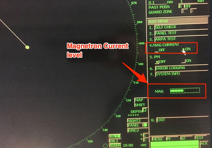
On JRC radars, click on the “Test” tab on the bottom right corner and turn the “Magnetron current” to on. Read the magnetron current reading.
Magnetron current should be between 5 ~ 9.5. If actual magnetron current is on higher side of this range, the magnetron is OK. In this case we may want to call the service technician to check (or replace) the PM unit.
Conclusion
Radars are eyes of the navigator. More so in these days when we rely more on radar for look out than on our eyes. But using the radar without proper settings would mean having a look out with half closed eyes.
Setting up the radar in a way to have all the targets plotted perfectly is as important as using the radar itself.
While the setting up procedure can change considerably with each make of the radar, it is important that we know how best to set up the radar. Setting up in a way to not to miss a single target on the screen, irrespective of how small it is.
Each of us must try our hands on these setting and should know what settings work when.
Share this:

About Capt Rajeev Jassal
Capt. Rajeev Jassal has sailed for over 24 years mainly on crude oil, product and chemical tankers. He holds MBA in shipping & Logistics degree from London. He has done extensive research on quantitatively measuring Safety culture onboard and safety climate ashore which he believes is the most important element for safer shipping.
Search Blog
52 Comments


very helpful

Happy to help Aniket

Thank you sir This is very helpful teaching methods...

Happy to help Pawan. let me know if you have any question any time.

sir why ror is based on heading of vessels & not on their actual track?

samarjeet, Not entire ROR is based on that. Only the rules under section "When in sight of one another" are based on the heading of the vessel. For rules under this section, we are supposed to take action when other vessel is in sight and looking at a vessel we can judge its heading and not course made good by it. This is explained in detail in Speed over water and speed over ground blog. Check that out. Let me know if you have any question anytime.

Hi.. I have question our x band radar pm test is 4.5 is that okey?.. The initial test during new magnetron replace is 7.5/18...My 2nd question is that there is a red circle on the radar screen on own ship. It suddenly appears what does it mean.. Hope you can help me with this.. Thanks you ver much

I am not sure what Make of Radar you have ? In any case you need to look into the Radar manual for Performance Monitor test. In case of JRC we need to look into the graph as shown in this blog and if the attenuation is more than 10db, magnetron need to be changed.

So it means when we use radar for collision avoidance in a RV case, the speed need not be STW?

I have to agree here that yes, it need not be STW in Restricted visibility. Would be glad to know your view point on this if you feel otherwise.

Hi Rajeev. This is me from a couple of months ago. To determine whether or not we are overtaking in RV, we need aspect of target vessel, right? That will come out of the radar plot which requires water speed. I think we require water speed in RV too. ☺

Hi Anand, I feel the overtaking word used in rule 19 has different context that rule no 13. It has nothing to do with the definition of overtaking as per rule 13. That is what I feel. What's your opinion on this ?

Hi Rajeev. You're right- overtaking is not defined under rule 19. However, the Rule allows an alteration to port for vessels forward of the beam that are being overtaken. So before accepting that liberty, we need to ensure we're overtaking... and in restricted visibility, i can't think of of a more acceptable method than the radar plot... for which I require the water speed (for aspect accuracy). In the absence of a definition for overtaking in restricted visibility, I would go with the definition in Rule 13 (coming up from a direction more than 22.5 degrees abaft the beam).Thanks Rajeev. :-) Anand.

Great work..thaks alot sir..i studied more info from ur blog..

Glad you are finding the information useful Daninda..

awesome article, I have spent hours reading radar manuals and I coulnd't get so much information, keep on posting, very good job...

Glad you found it useful Nicolas..

Very informative wish you would do one on Furuno FR8252. Had it for a few years and have not been able to find anyone familiar with the unit. Even Furuno techs seem to be less familiar with this unit.

Hi Skip, I will try to write on Furuno if I get my hands on a Furuno radar.

Sir pls write something on radar ie when to use true motion and relative motion and difference between true and relative vector and which one use when

Will right on that Ayush..

Would be nice to know that..its always a confusing one for me too..

Good day sir. i highly appreciate your kind effort in these article which is seem to be perfect radar hand user guide, specially for those need straightforward answer and punch line for this matter. Best regards.

Glad to hear that Aria..

How high does the radar beam see vertically. I imagine 3 degrees; is that about right? Thanks

hello sir...1 question for you.. What is another name for a calibration ring???

sir i have one doubt regarding cover pulse and main pulse. How do i observe them on oscilloscope. Please guide me on setting the oscilloscope. On our test bench we have waveform and signal generator as source. So, please help me out.

my radar is not working well.when i have hooked any contact it dose keep it properly at that time what can i do

it dose not keep properly

Info for kindergarden.

Good Day Rajeev, we have question regarding our radar (FURUNO MU201CR), how to fixed or adjust object on the screen if not on track (shifted clockwise at 0.5 NM)? Thanks alot in advance. Regards...

Thanks a lot sir for the valuble information

Very valuable information, also need to check how do we change TX time on JRC radar upon replacing magnetron. JRC JMA 9932SA

How can I write in the the pm range

thanks for very realistic information sir....not like in the manuals academic language.....could you please explain about tuning in JRC rasdar

My search for radar pm made me come here. The blog is very informative as well as educative. Keep up the good work. I didn't get a chance to do Radar PM while onboard because of the busy schedule and lack of time. So, my question is: is it possible to check radar performance by observing the concentric circles or arc that appear during PM Test? What should be the distance of circle with respect to ship?

Helpful and interesting article! Thank you! I seek clarification for another matter as well ... The radar equipment I use, is the same as the one described in your article. For a few days I've noticed an offset between the AIS target and the Radar target on the radar display. At first I thought there might be an issue with my GPS receivers so I've started investigating the problem in this direction. But, GPS receivers seemed to be working fine, satellites were connected, parameters were according with the maker's manual etc. With the first opportunity I've made few manual position fixes (by radar rng & brg) which resulted in a position offset of abt 2 cables. With the same offset values as shown by the ECDIS, I've adjusted the radar offset in the MAP DISPLAY SETTING menu --> Lat/Long correction. Now the radar image was alligned, AIS targets and Radar targets had the same position on the screen. Next watch when I come on duty, I see that the AIS targets and Radar Targets are again miss-aligned. (Nobody reset the offset in the mean time, were the same values typed by me) Then I start thinking there might be an issue with the radar itself.. So I entered the service-man menu, and performed adjustment of bearing and range from here. Basically I've aligned the radar echo with the AIS target - bearing of minus 2 deg from original value and rage from 350 units to 400. (I don't know what units are used for this range figures). Now the targets are aligned perfectly, and everything seems to be in order. But the question is: Where my adjustments in the service man menu right to do so, or I should NOT have entered there? How can I be 100% sure that now the radar shows the distances and bearings accurately?

What could be the reason for frequent loss of targets on nav radar? And the suggested remedial actions. Regards

Special Thanks for your blog.

Very good blog sir......stay healthy

I find myself blessed to have found your blogs terrifically seductive practical knowledge that it holds to shape a seafarer. I implore you to share as many practical maritime insights as is possible. Thankful to you triggering my knowledge up.

Can we reset the transmission and receiving switch to zero in jrc radar

I need to communicate my deference of your composing aptitude and capacity to make perusers read from the earliest starting point as far as possible. I might want to peruse more up to date presents and on share my musings with you. rpa training

Bonjour Madame, Monsieur - pays : cote d'ivoire Objet: demande de cotation RADAR nous souhaiterons avoir un correspondent de votre société pour une demande de cotation de RADAR (10.4 Multi-color LCD RADAR 1835/1935/1945) . avec 15m de Câble Bien Cordialement

Bonjour Madame, Monsieur - pays : cote d'ivoire Objet: demande de cotation RADAR nous souhaiterons avoir un correspondent de votre société pour une demande de cotation de RADAR (10.4 Multi-color LCD RADAR 1835/1935/1945) . avec 15m de Câble Bien Cordialement

how to best detect squals ? please advise

According to Value Market Research, the latest technology trends and global market opportunity analysis in the Marine AIS Monitoring Solution Market industry growing with a high CAGR in the upcoming year. Our report has categorized the market based on technology, service, development, vertical and region. https://www.valuemarketresearch.com/report/marine-ais-monitoring-solution-market

Great Share! Can we use of Solid State Radar instead of Magnetron Radar ?

Dear Capt Rajeev Jassal, thanks for your valuable articles. Regarding the radar performance test to be done every watch, what is the supporting regulation this is based on ? Is it a local MCA rule or international IMO rule ? My ship is not on UK flag. Thank you.
Leave Comment
More things to do on myseatime

MySeaTime Blogs
Learn the difficult concepts of sailing described in a easy and story-telling way. These detailed and well researched articles provides value reading for all ranks.

Seafarers Question Answers
Ask or answer a question on this forum. Knowledge dies if it remains in our head. Share your knowledge by writing answers to the question

MySeaTime Podcast
This podcast on the maritime matters will provide value to the listeners. Short, crisp and full of value. Stay tuned for this section.

Thank you.. For an useful information
Glad that you found it useful Vignesh
Why i am unable to post question capt.sir.